Tuesday, May 31, 2011

Reed block investigation

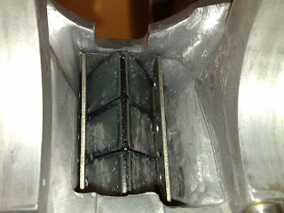
Today I did a final bit of grinding on the newly thickened reed block wall. I had to eat away at it a bit to get the reeds to fit. Also a bit of a tidy up and smoothing of the "flow lanes" was required. See first two pictures below.

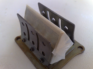
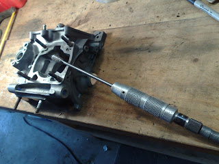
 These next two pictures show that the reed petal backstops actually inhibit the flow along the paths that I intended when I ported the case. However, the V-Force III brand reeds differ significantly in design and do not have a very large petal backstop. I am expecting that they will probably work quite well here as a result. I will probably have the cases all together by the time I get the V-Force III reeds, so pictures like these will not be possible. What a shame; readers will just have to "imagine" it. :-)

Today I also assembled the gearbox into the crankcase.

Monday, May 30, 2011

Added crankcase volume

I dropped of the burette to Wob this morning and stole a piece of 5mm thick aluminium plate off him.
Looks like I'll be getting a set of V-Force reeds through Wob. They won't be cheap, but I need to drop off the stuffers so he can have a little suss out of what bits will match up with the NSR. They may add as much as 2 horsepower (per cylinder!) across a broad chunk of the rev range. Seems hard to believe, but we'll see.
Then I cruised out to Tim's and shaped the plate to match the reed block wall on the upper cranckcase.
I then drilled a hole through the crankcase and alloy plate and bolted the two together.
Then I shaped it a bit more with the porting tools.
Once it was looking about right I unbolted the plate and bead blasted the relevant surfaces ready for the application of Devcon.
Mixed up some Devcon and applied it to the faces and bolted together.
Waited for it to harden up a bit and tidied up any stray blobs of Devcon.
Tomorrow, after it has fully set, I will give it a final grind with the porting tools.
It looks like the added volume will be very close to the required 12.5ml. I calculated it at 11.5ml + a bit extra for the Devcon. Not exact I know, but close enough for me.


Sunday, May 29, 2011

Crankcase bearings and barrel port edge grind

This morning I put most of my engine bits in a big box and went over to Tim's.
Used the paint stripper heat gun to warm up the main crankcase and Tim dropped in the bearings.
He also put in the clutch actuator bearings and seal. Gear change shaft bearing and seal.
Heated up the cassette gearbox plate and plonked in those bearings.
Assembled the gear shafts with their bearings.

########################################################

Bearing listing update 2018/05/05.
 

I have ordered a set of bearings and seals for the gearbox.
I thought I might as well post it up here for reference.

This is for MC21 and MC18 R5/6k. Possibly other models as well, but I am not sure about that.
Format in mm is: (ID-OD-width)

Bearings
1 x 6203-RS (17-40-12) Counter Shaft LH $5.43
1 x 6204-2RS (20-47-14) Output shaft RH $7.53
1 x 6205-2RS (25-52-15) Counter shaft RH $7.99
1 x 6305-RS (25-62-17) Output shaft LH $10.81
1 x NTN 7B HK 1412 (14-20-12) internal needle roller - Gear change shaft $7.82

Seals
1 x 12-19-5 Clutch actuator $3.45
1 x 14-24-6 Gear change shaft $3.80
1 x 25-47-7 Output shaft LH $5.29
2 x 9-18-7 Power valve shaft $3.57 each

I have left out the 2 small internal needle rollers that are up in the clutch actuator "tunnel".
They are 12-16-10 and 10-14-10
Also I have left out the selector drum bearing. Not too sure of its exact dimensions.
Prices are in $NZ and include 15% GST (Tax)
Total cost is NZ$59.25

########################################################

A special note about the Bearing that goes on the output shaft where the front sprocket goes for the final drive chain.
There is a transmission oil pump on the RH side of the engine. It pumps oil through a tricky little pathway in the crankcase and that oil comes out on the LH side of the front sprocket bearing.
In order for that oil to make its way back into the engine via specially located holes in the transmission shafts it is necessary to have the outer bearing seals installed on the LH transmission shaft bearings but not on the inside of the bearings. So make sure that the inner seals are removed and the outer seals are left in place on both LH gear shaft bearings before installing.

For a lot of detail on this see this post:
https://www.tapatalk.com/groups/nsr250/transmission-oil-pump-pathway-t589.html#p3332

##########################################################

Then I pulled out an old barrel and asked Tim to show me how best to use his comprehensive range of porting tools to smooth off the sharp lipped edges on the barrel ports.
I had a bit of a practice on the old barrel before continuing on with my good barrels.
This is a pretty minor tweak but I just wanted to maximise flow.
It was fun to do it once and was quite satisfying. I took my time, and if anything probably left very slight "lippage" rather than grind off too much. After the lip grinding, I went around all the edges with a polishing head and was careful to make the edges all smooth and non ring-grabby. Spent about 3 hours on the dremmel which is pretty slow going, but I was being overly cautious on purpose.

I also ate into the bottom of the transfer ports bridge wall. Just rounding it off. Apparently this is "The Go". I didn't argue or question it, I just did it under blind faith. Although, I have to admit that I had seen it done on other two stroke barrels before.


So now I just need to "Dev Con" in a 6mm plate (12.5cc's) of aluminium against the left most reed block wall on the crankcase to get the two primary compression volumes equal and then I can assemble the engine in its entirety.
I am hoping that these little porting tweaks will present as real horsepower in the long term, but even if that is not the case, I have been happy to play about and try to get things reasonably optimal anyway. It's fun.

Arrived Tim's approx 10:30. Left Tim's approx 7:30.

Saturday, May 28, 2011

Crankcase volumes measured

OK , well, after a few stuff ups I finally got what I believe to be quite accurate volume readings.
I suspect that the error in the difference in volumes is less than 1ml. Seriously!
The error in the absolute value of the readings is possibly out by more than this.
This is because I did not check the volumetric accuracy of the measurement marks on the larger container.
The biggest hassle was sealing off the reed block. In the end I just squirted heaps of silicone liquid gasket into the back of the red block, after using masking tape to hold the reeds shut.

Top Left Volume: 605.5 ml
Bottom Right Volume: 593 ml.

Note that these measurements were taken AFTER I had ported the Top Left crankcase volume.
So now I am going to attach a piece of 5mm thick aluminium plate to the left most reed block wall on the crankcase to fill in a volume of approx 12.5 ml.

Somehow I can't help but think that this then makes the crankcases conform to how the Honda engineers originally intended them to be. I think production restrictions for the crankcase castings meant that they could not cost effectively achieve this desired optimum.

Friday, May 27, 2011

Crankcase Volume Measurement - First Pour

Last night I sealed off the exhaust port against the piston with Blu-tak.
Then I began to pour oil into the crankcase through the hole in the piston with the piston at TDC.
I started off with 300 ml, then added 25ml at a time via the burette that I borrowed off Wob.
After about 8 burette-fuls, I noticed oil starting to leak out in several places, but it was just a slow weep. I ended up doing 15 and a bit burette-fuls of oil to get the crankcase full up to the hole in the piston.

So this was a bit of a disaster due to the leakage. I will have to pull it apart and seal it up properly for another run.
However, at least I now have a good starting volume to work with.

Basically, it took 613 mls with about 50ml of leakage.
I checked these figures with the volume of oil that I ended up pouring out of the crankcase.
613ml - 50ml = 563ml
I poured 560ml out of the crankcase.

So lets say as a rough guide that the crankcase volume holds (560ml - 125cc) = 435mls.
This gives a primary compression ratio of 560/435 = 1.29. (OK this is a bit basic, but forgive me)
According to Wob, this is at the top of the "normal" range of 1.2 to 1.3.
Not too sure what "normal" is referring to here, but I guess he means normal for a road racing engine with this sort of bore/stroke ratio??

Anyway, I'll seal it all off properly and bolt it up and do it all again on both cylinders/volumes and hopefully get a good handle on things.

Oh, no pictures of pouring from burette as that would require 3 hands.


Thursday, May 26, 2011

Prepare to measure crankcase volumes

Yesterday I drilled a hole in the top of 2 old pistons and taped up the reed valves.
Then I assembled the crankshaft into the crankcases and bolted on the reed blocks.
Now I am ready to pour some automatic transmission fluid into the crankcase through the hole in the piston with the piston at Top Dead Centre. Note that the crankcase volume is to include the volume of the transfer ports which cannot be done with the piston at Bottom Dead Centre. So I will have to subtract approx. 125cc from each of my 2 volume measurements.


I want to work out if the porting I did on the top left crankcase has made any real difference to the  crankcase volume. I am thinking that I will need to fill in the crankcase a bit to get the 2 volumes the same.
As you can see in the photo below; the LH side reed block wall is not the same as the others. I am thinking that I can fill the crankcase volume here to make it match up with the rest.

Crankcase flow


23rd March 2011


This afternoon I popped out to Tim's and jumped on his "porting bench".
Without really knowing what I was doing I flowed the rear of the (left cylinder side) top cylinder base to achieve nice flow up into the transfers. It was pretty simple and I really enjoyed doing it.
I guess I probably spent about 2 hours just taking my time, faffing about.


25th March 2011


This morning I put the crankcase halves together and placed the barrels on to look to see if I could match up any surfaces to get fractionally better flow.
Mainly the front right cylinder crankcase area where the two halves meet required slight tweakage.
Very hard to physically look at flow from crankcase into barrel.


Also, for an even better job, see the flow work TSRL did on his blog here.

Monday, May 23, 2011

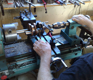
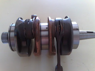
NSR250 MC18 Crankshaft rebuilt

20th March 2011

I am posting this a couple of months late.

My MC18 crankshaft has been pressed back together.
I paid Wob $80 for the 2 big end bearings and owe him a further $200 for pressing the crank together.


NSR250

NSR250 Crankshaft bearings and seals: Availability

Tauranga Massage